Having experimented with the use of basswood/linden to build smaller model ships, I decided to use the skills I had acquired to tackle a somewhat larger and more complex warship. I chose the German pre-dreadnought battleship Schleswig-Holstein (as she appeared in 1939) as the basis of my design.


Tools
I used the tools shown in the following photograph to build my model:

They include:
Some basics
The hull was constructed in two parts, and lower hull and an upper hull. This was done so that it was possible to model the distinctive gun casemates carried by the Schleswig-Holstein.
The lower hull was constructed from two 8"/20cm and eight 2"/5cm long pieces of 0.5"/12.5mm x 0.5"/12.5mm basswood.

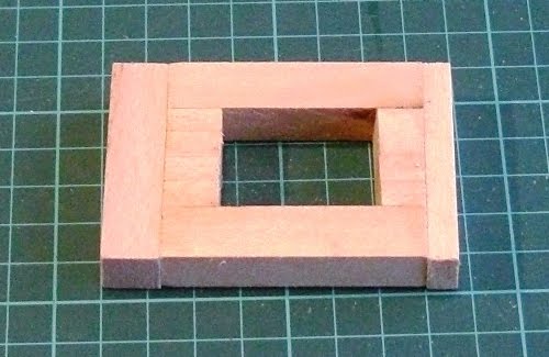
The shorter pieces were glued together to form blocks at either end of the model and the sides were then glued on to form a hollow rectangle.

The upper hull was constructed from two 8"/20cm and sixteen 2"/5cm long pieces of 0.375"/9mm x 0.25"/6mm basswood.

These were also glued together to form a hollow rectangle.

A piece of 3"/75mm x 8"/20cm x 0.25"/6mm basswood was used as the bottom of the lower hull. The position of the hole in the hollow rectangle was marked on the basswood and small blocks were glued in place to act as guides/tabs to hold the two pieces in place when they were glued together.

A piece of 3"/75mm x 8"/20cm x 0.125"/3mm basswood was used as the top of the upper hull. It also had guides/tabs glued to it.

The two parts of the lower hull were then glued together ...

... as were the two parts of the upper hull.

The excess 0.125"/3mm thick basswood was carefully trimmed off the upper hull and pieces 0.375"/9mm x 0.25"/6mm basswood were cut to form the shape of the casemates. These were then glued in place.

The excess 0.125"/3mm thick basswood at each end was carefully trimmed off the upper hull. Because Schleswig-Holstein had a very distinctive stepped-down stern, a small 0.25"/6mm section of the stern block was carefully sawn off.

Tabs/guides were then glued into place ...

... and the upper and lower parts of the hull were glued together.
The rough shapes of the bow and stern were then sawn off ...

... and then carefully sanded smooth.

Tab/guides for the superstructure were then glued into place.

The Superstructure
The superstructure was constructed in a very similar manner to that used to build the upper and lower parts of the hull.
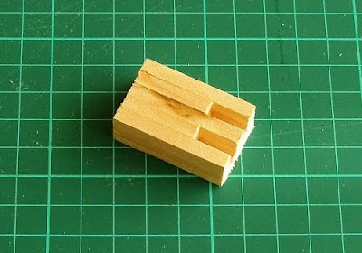
The main part of the superstructure was constructed two 2.25"/5.7cm and four 0.5"/12.5mm long pieces of 0.5"/12.5mm x 0.5"/12.5mm basswood.

These were glued together to form a hollow rectangle. A 2"/5cm x 0.5"/12.5mm x 0.5"/12.5mm piece of basswood was glued to the front end of the hollow rectangle and a 2"/5cm x 0.5"/12.5mm x 0.25"/6mm piece of basswood was glued to the back end of the hollow rectangle ...

... thus.

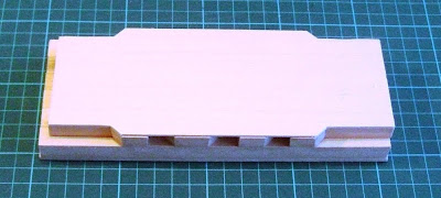
A 2"/5cm x 3"/7.5cm x 0.25"/6mm piece of basswood was then glued to the top of the hollow rectangle to form the main part of the superstructure. A 2"/5cm x 1"/25mm x 0.25"/6mm piece of basswood was then glued across the end of the top of the block to form the rear of the superstructure and two pieces of 2"/5cm x 0.375"/9mm x 0.25"/6mm basswood were glued along the centre of the superstructure, forming a 'T' shaped raised area atop the superstructure.

The front and rear corners of the superstructure block were then cut off. (The corners were trimmed off at angle of 45 degrees. The front corners were trimmed off by 0.25"/6mm and the rear corners by 0.375"/9mm.)

1"/25mm long bridge wings made from 0.375"/9mm x 0.25"/6mm basswood were then glued to the front of the superstructure block and two pieces of 0.25" thick basswood were glued to either end of the superstructure block. The rearmost piece was 1.125"/28mm wide and the foremost piece was 1.375"/35mm wide. The outer edges of both pieces of basswood were rounded off before being glued into place.

A piece of 2"/5cm x 1"/2.5cm x 0.125"/3mm basswood was glued on top of the bridge wings and front end of the superstructure block after the front corners of the piece of basswood had been cut off at an angle of 45 degrees 0.5"/12.5mm from the back.
The rest of the superstructure components were then assembled. The bridge and distinctive foremast was constructed from a 0.75"/18mm x 0.75"/18mm x 0.625"/15mm block of basswood (the fore bridge), a 2.75"/7cm long piece of 0.375"/9mm dowel (the mast), a 0.75"/18mm long piece of 0.5"/12.5mm dowel (the fire director), a 0.5"/12.5mm x 0.375"/9mm x 0.25"/6mm basswood (the mast platform), and two short pieces of cocktail stick (one used to form the arms of the rangefinder and one to act as a support for the mast platform). 0.375"/9mm holes were drilled through the bridge block and the mast platform and into the fire director.
The rear mast was a 2.5"/6.25cm long piece of 0.375"/9mm dowel (the mast), which was to be fixed into a 0.75"/18mm x 0.75"/18mm x 0.625"/15mm block of basswood (the rear bridge). A 0.375"/9mm hole was drilled into the block to accept the lower end of the mast.
Note that short pieces of cocktail stick have been glued into several of the pieces, and corresponding holes have been drilled into the superstructure block. This assists in the correct placing of the pieces when assembly takes place and reinforces the glued joints.

The final parts of the superstructure to be constructed were the funnels. The foremost funnel has a very distinctive shape as it was the result of the original two funnels being trunked together. It was constructed from two pieces of 0.5"/12.5mm x 0.5"/12.5mm basswood (one of which was 1.5"/37.5mm long and the other [which was cut off at an angle of 45 degrees] was 0.75"/18mm long) and a piece of 0.375"/9mm x 0.5"/12.5mm x 1.5"/37.5mm basswood. The rearmost funnel was made from a piece of 0.5"/12.5mm x 0.5"/12.5mm x 1.5"/37.5mm basswood.

The edges of both funnels were rounded off to produce the 'flat-sided, rounded-ended' look of the original funnels.

The Turrets
Two turrets were constructed, and from the outset I decided that they would have to be capable of turning.
The main part of each turret was constructed from pieces of 0.375"/9mm x 0.1875"/4.75mm basswood. Three pieces (which formed outer sides of the turret and the middle part of the turret) were 1.5"/37.5mm long and two pieces (which were used as spacers) were 1"/25mm long.

These pieces of basswood were glued together and then glued to a piece of 1.5"/37.5mm x 0.9375"/24mm x 0.125"/3mm basswood. The latter formed the base of the turret.
Another piece of 1.5"/37.5mm x 0.9375"/24mm x 0.125"/3mm basswood was then glued to the top of the turret to form its roof.

The length of the turret was then reduced to 1.25"/31mm by sawing off 0.125"/3mm from each end of the turret. This was done to ensure that the end of the turret were flat prior to sanding. The corner of the turret were then rounded off by careful sanding.

A 0.09"/2.5mm hole was then drilled into the bottom of the turret and a 0.75"/18mm long piece of 0.09"/2.5mm diameter dowel was glued into the hole. This was to be used as the turret spigot around which the turret would be able to rotate.
A circular piece of 0.125"/3mm thick basswood (with a diameter of 1.5"/37.5mm) was then glued to the bottom of the turret, with the dowel placed through the centre point of the circle.

The gun barrels (which were 1"/25mm lengths of 0.1875"/4.75mm dowel) were then glued into the holes on the front face of the turret.

Final Assembly
All that remained was to bring the various parts together and assemble them.
First the superstructure block was glued to the hull. Two 0.125"/3mm diameter holes were drilled into the hull to accept the turret spigots.

The fore bridge, funnels, and rear bridge were then glued to the superstructure block. The foremast was also assembled, as was the fire director.

The fore and read masts were then glued in place and the turrets were mounted.

The main construction process was then complete and the model was ready for painting.


Tools
I used the tools shown in the following photograph to build my model:

They include:
- PVA Wood Glue
- A razor saw
- A craft knife/box opener
- A steel ruler
- An aluminium mitre block
- A number of modelling clamps
- Two types of emery board
- A triangular set square
- Two pin vices (each holding a different sized drill bit)
- A pencil
Some basics
- Remember to use any tools carefully so that you do not risk injuring yourself.
- Always let the glue 'cure' before you attempt to move on to the next stage in the production process. (The PVA Wood Glue that I use usually takes about an hour to 'cure' but does not reach its maximum strength for twenty four hours.)
- Always clamp and/or support any glued joints until the glue has 'cured'.
The hull was constructed in two parts, and lower hull and an upper hull. This was done so that it was possible to model the distinctive gun casemates carried by the Schleswig-Holstein.
The lower hull was constructed from two 8"/20cm and eight 2"/5cm long pieces of 0.5"/12.5mm x 0.5"/12.5mm basswood.

The shorter pieces were glued together to form blocks at either end of the model and the sides were then glued on to form a hollow rectangle.

The upper hull was constructed from two 8"/20cm and sixteen 2"/5cm long pieces of 0.375"/9mm x 0.25"/6mm basswood.

These were also glued together to form a hollow rectangle.

A piece of 3"/75mm x 8"/20cm x 0.25"/6mm basswood was used as the bottom of the lower hull. The position of the hole in the hollow rectangle was marked on the basswood and small blocks were glued in place to act as guides/tabs to hold the two pieces in place when they were glued together.

A piece of 3"/75mm x 8"/20cm x 0.125"/3mm basswood was used as the top of the upper hull. It also had guides/tabs glued to it.

The two parts of the lower hull were then glued together ...

... as were the two parts of the upper hull.

The excess 0.125"/3mm thick basswood was carefully trimmed off the upper hull and pieces 0.375"/9mm x 0.25"/6mm basswood were cut to form the shape of the casemates. These were then glued in place.

The excess 0.125"/3mm thick basswood at each end was carefully trimmed off the upper hull. Because Schleswig-Holstein had a very distinctive stepped-down stern, a small 0.25"/6mm section of the stern block was carefully sawn off.

Tabs/guides were then glued into place ...

... and the upper and lower parts of the hull were glued together.

The rough shapes of the bow and stern were then sawn off ...

... and then carefully sanded smooth.

Tab/guides for the superstructure were then glued into place.

The Superstructure
The superstructure was constructed in a very similar manner to that used to build the upper and lower parts of the hull.
The main part of the superstructure was constructed two 2.25"/5.7cm and four 0.5"/12.5mm long pieces of 0.5"/12.5mm x 0.5"/12.5mm basswood.

These were glued together to form a hollow rectangle. A 2"/5cm x 0.5"/12.5mm x 0.5"/12.5mm piece of basswood was glued to the front end of the hollow rectangle and a 2"/5cm x 0.5"/12.5mm x 0.25"/6mm piece of basswood was glued to the back end of the hollow rectangle ...

... thus.
A 2"/5cm x 3"/7.5cm x 0.25"/6mm piece of basswood was then glued to the top of the hollow rectangle to form the main part of the superstructure. A 2"/5cm x 1"/25mm x 0.25"/6mm piece of basswood was then glued across the end of the top of the block to form the rear of the superstructure and two pieces of 2"/5cm x 0.375"/9mm x 0.25"/6mm basswood were glued along the centre of the superstructure, forming a 'T' shaped raised area atop the superstructure.

The front and rear corners of the superstructure block were then cut off. (The corners were trimmed off at angle of 45 degrees. The front corners were trimmed off by 0.25"/6mm and the rear corners by 0.375"/9mm.)

1"/25mm long bridge wings made from 0.375"/9mm x 0.25"/6mm basswood were then glued to the front of the superstructure block and two pieces of 0.25" thick basswood were glued to either end of the superstructure block. The rearmost piece was 1.125"/28mm wide and the foremost piece was 1.375"/35mm wide. The outer edges of both pieces of basswood were rounded off before being glued into place.

A piece of 2"/5cm x 1"/2.5cm x 0.125"/3mm basswood was glued on top of the bridge wings and front end of the superstructure block after the front corners of the piece of basswood had been cut off at an angle of 45 degrees 0.5"/12.5mm from the back.
The rest of the superstructure components were then assembled. The bridge and distinctive foremast was constructed from a 0.75"/18mm x 0.75"/18mm x 0.625"/15mm block of basswood (the fore bridge), a 2.75"/7cm long piece of 0.375"/9mm dowel (the mast), a 0.75"/18mm long piece of 0.5"/12.5mm dowel (the fire director), a 0.5"/12.5mm x 0.375"/9mm x 0.25"/6mm basswood (the mast platform), and two short pieces of cocktail stick (one used to form the arms of the rangefinder and one to act as a support for the mast platform). 0.375"/9mm holes were drilled through the bridge block and the mast platform and into the fire director.
The rear mast was a 2.5"/6.25cm long piece of 0.375"/9mm dowel (the mast), which was to be fixed into a 0.75"/18mm x 0.75"/18mm x 0.625"/15mm block of basswood (the rear bridge). A 0.375"/9mm hole was drilled into the block to accept the lower end of the mast.
Note that short pieces of cocktail stick have been glued into several of the pieces, and corresponding holes have been drilled into the superstructure block. This assists in the correct placing of the pieces when assembly takes place and reinforces the glued joints.

The final parts of the superstructure to be constructed were the funnels. The foremost funnel has a very distinctive shape as it was the result of the original two funnels being trunked together. It was constructed from two pieces of 0.5"/12.5mm x 0.5"/12.5mm basswood (one of which was 1.5"/37.5mm long and the other [which was cut off at an angle of 45 degrees] was 0.75"/18mm long) and a piece of 0.375"/9mm x 0.5"/12.5mm x 1.5"/37.5mm basswood. The rearmost funnel was made from a piece of 0.5"/12.5mm x 0.5"/12.5mm x 1.5"/37.5mm basswood.

The edges of both funnels were rounded off to produce the 'flat-sided, rounded-ended' look of the original funnels.

The Turrets
Two turrets were constructed, and from the outset I decided that they would have to be capable of turning.
The main part of each turret was constructed from pieces of 0.375"/9mm x 0.1875"/4.75mm basswood. Three pieces (which formed outer sides of the turret and the middle part of the turret) were 1.5"/37.5mm long and two pieces (which were used as spacers) were 1"/25mm long.

These pieces of basswood were glued together and then glued to a piece of 1.5"/37.5mm x 0.9375"/24mm x 0.125"/3mm basswood. The latter formed the base of the turret.

Another piece of 1.5"/37.5mm x 0.9375"/24mm x 0.125"/3mm basswood was then glued to the top of the turret to form its roof.

The length of the turret was then reduced to 1.25"/31mm by sawing off 0.125"/3mm from each end of the turret. This was done to ensure that the end of the turret were flat prior to sanding. The corner of the turret were then rounded off by careful sanding.

A 0.09"/2.5mm hole was then drilled into the bottom of the turret and a 0.75"/18mm long piece of 0.09"/2.5mm diameter dowel was glued into the hole. This was to be used as the turret spigot around which the turret would be able to rotate.
A circular piece of 0.125"/3mm thick basswood (with a diameter of 1.5"/37.5mm) was then glued to the bottom of the turret, with the dowel placed through the centre point of the circle.

The gun barrels (which were 1"/25mm lengths of 0.1875"/4.75mm dowel) were then glued into the holes on the front face of the turret.

Final Assembly
All that remained was to bring the various parts together and assemble them.
First the superstructure block was glued to the hull. Two 0.125"/3mm diameter holes were drilled into the hull to accept the turret spigots.

The fore bridge, funnels, and rear bridge were then glued to the superstructure block. The foremast was also assembled, as was the fire director.

The fore and read masts were then glued in place and the turrets were mounted.

The main construction process was then complete and the model was ready for painting.


Hi Bob,
ReplyDeleteThat is a supremely useful guide and very inspirational!
She looks really nice and I wonder if you had made the funnels removable/interchangeable you could have used her as built as well.
I can'wait to see her painted and some opposition as well!
All thebest,
DC
David Crook,
ReplyDeleteThanks for the very kind comments.
Making the funnels interchangeable might have been a step too far ... but it is something that I may well consider for the future.
I have one or two minor alterations and additions to make to the model before I paint her, but with luck that will be done by the weekend.
All the best,
Bob
My goodness Bob.
ReplyDeleteYou put a lot into that!
I can see you will get a lot out of it now!!
Well done.
Jim
Jim Duncan,
ReplyDeleteIt was a labour of love ... well a labour, anyway!
I have plans to build a Russian opponent sometime soon using a similar method of construction.
All the best,
Bob
classic stuff, well done.
ReplyDeleteJohn Curry,
ReplyDeleteMany thanks for your comment.
Wait until I have a fleet of them!
All the best,
Bob
Looks like way too much hard work, even for a chap eith time on his hands!
ReplyDeleteDoes look nice tho'
Bob
ReplyDeleteThanks for the details. I think I have all the tools you've shown - except the skill and patience!
PD
Excellent guide! Think I'll have a go!
ReplyDeleteTrebian,
ReplyDeleteI suspect that it was no harder for me to make than it was for you to create your latest game ... which - by the way - looks like a great!
I suppose that it just an example of different horses for different courses.
All the best,
Bob
Peter Douglas,
ReplyDeleteThanks for your kind comment.
Before I started my recent model shipbuilding spree I had no skill and very little patience. Now I have a bit of both ... which is no bad thing!
Give it a try yourself. You never know, you might be quite good yourself once you have.
All the best,
Bob
Don M,
ReplyDeleteI am pleased if my guide has been of some help and encouragement to you, and I look forward to seeing how you get on.
All the best,
Bob